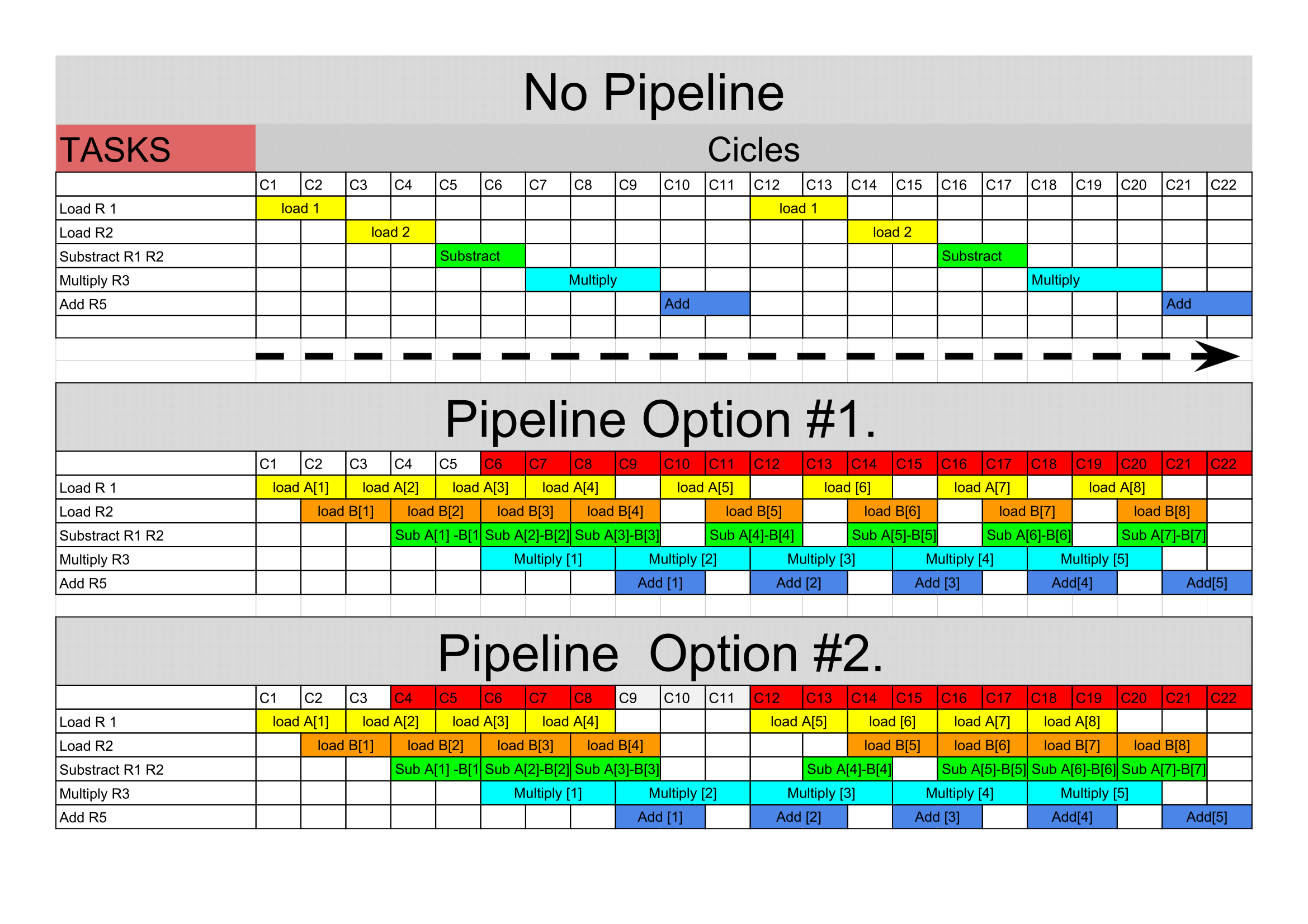
Basic Example on Pipelining, OoO Execution and architecture (Hmw2).
*OoO (Out of order)
This example was an exercise proposed by Dr. Rémi Mégret in M6786 Class.
We consider a multi-issued super scalar processor. At each cycle, the following instruction can be issued simultaneosly:
1 load or store + 1 FP addition or substraction + 1 FP multiplication. (FP: Floating Point)
The latencies (pipeline depth) of the instructions are as follows: Load/store : 2 cycles; FP adition: 2 cycles; FP muliplication: 3 cycles.
For simplicity we assume that:
-
All other operations (inicialization,loop/branch, integer arithmetic…) Come at no cost.
-
There is no additional latency with memory (no cache miss)
Therefore only load, FP sub, FP add and FP mult marked in bold in the code will be taken in consideration.
#        i=0
#        R5=0 // Note: R# corresponds to register number #
   loop: load A[i] into R_1
         sub R_3 = R_2 -R_1
         mult R_4= R_3 * R_3
         add R_5 = R_5 + R_4
#        i=i+1
#        branch to loop if i<N
#        store R5 into s
The chronogram:
There are several ways to represent a pipeline that perform this process. In this case, I will represented it taking in consideration each task (load 1, load 2, sub, mult and add) in a different line, the full instruction will be done after it gets to the bottom of the pipeline. And the next instruction will be read in the columns at the right.

No pipeline:
As we observed in the graph. In case that we run a no-pipeline process, we will take 11 cycles to perform just one instruction. Therefore the throughput would be \(\sim\) 0.09 instructions per cycle.
Pipeline.
Now we want to speed up this process and we decide to use a pipeline. The second and third diagram explains this clearly. Though we have to wait eleven cycles (wind-up phase) to have the first output, after that every 3 cycles we will have a new result. Thus, we have improved the troughput almost 300% per cycle. In the same 22 cycles depicted instead of having 2 instructions ready, we have 5.
Note that the pattern starts after the 5th cycle. The reason is that we cannot schedule more substractions in line, because if we do so, after substracting the third element (A[3]-B[3]), we would overwrite its information causing a wrong multiplication at the [4] instruction. That is also why we need to stall the loading unit in the 4th cycle untill that substraction has been processed. Thereafter the pattern is the same.
Troughput.
By definition we will consider troughput as the “amount of work done in a given time” [patterson][1]. In this case we will use the clock cycle of the processor. For instance, the troughput of the first diagram would be: 1/11. Because in a single cycle that portion of the entire instruction is processed. However, in the second diagram we have that every 3 cycles (with n big enough) we have an instruction complete, which represent 0.33 throughput.
In the second and third pipeline the troughput is 3.6 higher than in a no-pipeline processor.
Even though the second and third processor have different scheduling, the throughput does not change. The reason is that the multiplication is the critical operation wich latency, no matter how good I organize the information, is always 3 cycles.
Architecture Diagram.
One possible processor design to perform this operation, would need esentially four components: The Fetch-Decode unit, the load/store, the FP Multiplication and the FP addition/substraction unit. I suggest the following architecture would work efficiently:

Since we have out-of-order execution is necessary to have a fetch-decode unit that schedule the orders. Then we have a separate unit to perform each of the different task, however only three different operation can take place at each cycle in this processor. In the end there is the commit unit that wraps all the results and reorder them in the right place, to finally store them back in the main memory.
Discussion:
As we appreciated the critical point is related to the multiplication unit. That unit is working all the time, however because of its latency, all the other units are not used to its full potential. Since they have one cycle each of stall.
